

One of the primary jobs the sales and marketing team at RK2 has with relation to UltraViolet (UV) water treatment systems-is customer education. 'Why is that?' you may ask. Unfortunately, while the concept of UV treatment appears simple, the actual application of the technology is anything but. In fact, capable OEM suppliers take great care to ensure that the customer is able to meet their actual treatment needs, in all practical operational scenarios, today, and as the system ages.
In many cases a potential customer may notice that one quote for a UV product may come in at a significantly higher cost than that of another. Good news, right? Lowest bid wins!
Well, perhaps the company that provided the lowest bid wins, but the real loser may be the customer. In the UV treatment industry, as in many others, it is the hidden or unknown factors that can greatly impact whether your system actually delivers the intended UV dose, or 'treatment', or not. In fact, UV water treatment is such a complex technology that the USEPA and other regulatory bodies worldwide have standardized sizing and application regulations for municipal drinking water and waste water.
While aquaculture does not abide by regulations per se (there are regulated aquaculture applications in some countries), capable OEM suppliers use these regulations as guidelines to ensure that the customer has the treatment they require when they purchased their UV system-to ensure adequate protection of their investments at all times.
As with any technology, fundamental knowledge is key to understanding the products you purchase. As a customer, being an expert in a given technology is not required. However, the more knowledge you have, the more likely you are to be a satisfied customer. To that end, it may be helpful to explain some of the key areas of interest with regards to UV water treatment.
UV Spectrum - There are four primary parts of the UV spectrum: UV-A and UV-B can make it through the earth's atmosphere. UV-C and UV Vacuum are blocked by the earth's atmosphere. In disinfection typically only UV-C is used.
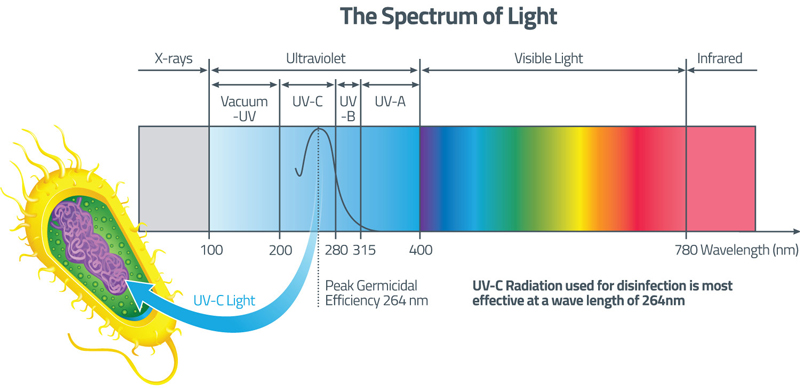
Figure 1 - Spectrum of Light
UV-C Intensity - The amount of UV-C light that is emitted by a light source is called the 'lamp intensity'. This is typically listed as mW/cm2. UV-C for disinfection is usually measured only at the wavelength of 254nm and is not visible to the human eye.
UV-C Dose - This is fairly easy to understand. It is the lamp intensity (mW/cm2) x time. Dose units are typically listed as mJ/cm2. Lamps with higher UV-C intensity can have the target organisms exposed to light for a shorter period of time than would lower power lamps, for the same overall dose. They both are equal in effectiveness; if the final delivered dose is the same. Contrary to popular belief, UV-C is not used to 'kill' organisms at the doses commonly prescribed. Organisms are inactivated by UV and are not able to reproduce-a harmful bacteria that cannot reproduce does no harm. It so happens that UV-C photon energy has the capability to inactivate organisms over a broad range of the spectrum, with 262nm being at the peak of this curve. The closer the light energy wavelength is to 262nm, the more effective the photons are at inactivation. The accepted wavelength range for disinfection is typically from 220nm-to-280nm.
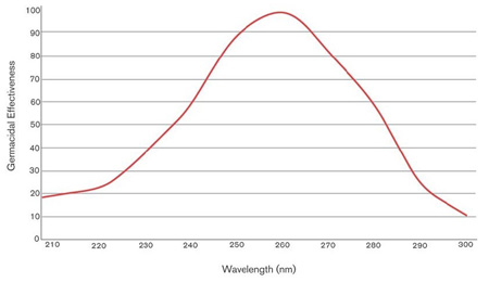
Figure 2 - Disinfection Effectiveness of UV Wavelengths
Okay, so now we know that UV-C, particularly at 254nm, can inactivate organisms. But do all organisms need the same dose to be inactivated? No, they do not. Figure 2 lists some common 'Dose Response Curves' of organisms of concern.
| ALGAE | UV DOSE |
|---|---|
| Chlorella vulgaris | 22 mJ/cm2 |
| BACTERIA | UV DOSE |
| Aeromonas salmonicida | 3.6 mJ/cm2 (log-3) |
| Pseudomonas fluorescens (fin rot) | 11 mJ/cm2 (log-3) |
| Listeria monocytogenes | 16 mJ/cm2 (log-5) |
| Streptococcus sp. (seawater) | 20 mJ/cm2 |
| Bacillus subtilis (spores) | 22 mJ/cm2 (log-3) |
| Vibrio anguillarum | 30 mJ/cm2 |
| Yersinia ruckeri | 30 mJ/cm2 |
| BKD (Bacterial Kidney Disease) | 60 mJ/cm2 (estimate) |
| Flavobacterium psychrophilum (Salmonid Bacterial Coldwater Disease) | 126 mJ/cm2 |
| Vibrio sp. (oyster) | 155 mJ/cm2 |
| FUNGI | UV DOSE |
| Saprolegnia diclina (zoospores) | 40 mJ/cm2 - 170 mJ/cm2 |
| PROTOZOA | UV DOSE |
| Sarcina lutea (Micrococcus luteus) | 26 mJ/cm2 (log-3) |
| Ceratomyxa shasta | 30 mJ/cm2 (log-3) |
| Perkinsus marinus (dermo disease) | 30 mJ/cm2 |
| Trichodina sp. | 35 mJ/cm2 (log-3) |
| Myxobolus cerebralis (TAMs, Whirling Disease) | 40 mJ/cm2 |
| Ichthyophthirius multifiliis (freshwater white spot) | 100 mJ/cm2 |
| Amyloodinium ocellatum | 105 mJ/cm2 |
| Trichodina nigra | 159 mJ/cm2 |
| Cryptocaryon irritans (marine white spot) | 280 mJ/cm2 |
| Costia necatrix | 318 mJ/cm2 (log-3) |
| VIRUS | UV DOSE |
| KHV (koi herpesvirus) | 4 mJ/cm2 |
| ISA (Infectious Salmon Anemia) | 8 mJ/cm2 |
| CCV (Channel Catfish Virus) | 20 mJ/cm2 |
| IHNV (Infectious Hematopoietic Necrosis/CHAB) | 20 mJ/cm2 |
| OMV (Oncorhynchus masou Virus) | 20 mJ/cm2 |
| IHNV (Infectious Hematopoietic Necrosis/RTTO) | 30 mJ/cm2 |
| VHS (Viral Hemorrhagic septicemia) | 32 mJ/cm2 |
| CSV (Chum Salmon Virus) | 100 mJ/cm2 |
| AHNV (Atlantic Halibut Nodavirus) | 105 mJ/cm2 |
| IPNV (Infectious Pancreatic Necrosis Virus) | 246 mJ/cm2 |
| Log-1 = 90%, Log-2 = 99%, Log-3 = 99.9%, Log-4 = 99.99%, Log-5 = 99.999% | |
| UV doses not accompanied by a specific log value, should be considered a minimal dosage. The listed data was collected from various sources and RK2 Systems, Inc. does not accept any responsibility for the accuracy of this information. This information is meant to be a guideline and should be used as such. | |
Figure 3 - Some Dose Inactivation Data
The collimated beam is a laboratory device designed to deliver precise doses to the samples of the organism in question. The dose response curves are generated by exposing the organisms of concern to various doses. The dose, in mJ/cm2, that was used to reduce the number of organisms logarithmically, is then determined. A viable organism, or one that is not inactivated, is identified after exposure, as it does reproduce. The inactivated organisms do not reproduce. By comparing the inactivated to still active organism, we can understand the reduction in viable organisms in our water. For example, if a liter of water had 10,000 viable target organisms and you delivered a three-log reduction, you would now have 10 viable organisms - 10,000 to 1,000 (one log) to 100 (two log) to 10 (three log).
Now that you understand UV-C, UV Dose and log reduction, we will discuss UV system light sources. There are some key factors that you should be aware of when selecting a specific lamp type in a UV treatment system.
Mercury has been safely used in UV lamps for over a hundred years. In fact, it is very likely that the water you drink every day, whether it be from a tap or a bottle, was treated by a UV system. Mercury is used in lamps because the mercury emits photons, primarily at the 254nm wavelength (nm is short form for nanometer) when excited by an electrical discharge - and this 254nm emission is right near the peak of microbiological inactivation for most organisms of concern.
There are two families of mercury-based lamps used in disinfection - monochromatic lamps that emit primarily at 254nm, and polychromatic lamps that emit with a broad spectrum, where the usable disinfection wavelength range is from 220nm to 280nm. Low-pressure, low-pressure high-output and amalgam lamps are all considered monochromatic in output. Medium-pressure lamps are considered polychromatic.
Lamp efficiency is overlooked by many people, however, if electrical power consumption is important to you, you may want to consider this factor. Lamp efficiency is the ratio of the amount of UV-C output of the lamp, as compared to the electrical input. Efficiency can range from ~35 percent or more for some light sources, to as low as a few percent for others.
There are three primary types of light sources used in aquaculture UV water treatment.
Low-Pressure and Low-Pressure High-Output lamps - These are the most efficient lamps at about 35 percent, or even more. However, these lamps are also relatively low power, so more lamps are required for a given application. In addition, these lamps are more sensitive to changes in water temperature - water temperatures must be taken into account by the system designers. This type of lamp is typically very reliable. These lamps are considered to be monochromatic, as the useful UV-C output is almost all at 254nm.
These lamps like to run at about 40°C for maximum output.
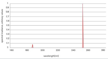
Figure 4 - Typical LP, LPHO and Amalgam Lamp Output Wavelengths (Note: 185nm wavelength is typically blocked for disinfection applications)
Amalgam Lamps - These are the primary 'go to' lamps in many treatment systems. In addition to high efficiency in the 33-to-35 percent range, they have relatively high intensity, and great reliability. These lamps like to run at roughly ~110°C for maximum output. All of these factors allow for an efficient, thermally stable and relatively compact system design.
Medium-Pressure (high-pressure) Lamps - Oversimplifying, medium-pressure lamps are basically low-pressure lamps with more mercury and driven with much higher currents and voltages. When mercury lamps are overdriven, they do not glow anymore, they create an arc. These arcs emit 254nm predominately, but also emits many other wavelengths. Some of these wavelengths are in the useful 220nm to 280nm range-remember our inactivation curve? At 254nm these lamps are only about 8% efficient, however, if considering the range of 220-to-280nm for inactivation they are about ~11 percent efficient. In addition, medium-pressure lamps like to run at about 600 to 900°C. That is very hot. As well, these lamps operate at higher voltages and currents, which again can create some challenges to system designers. So why use them you may ask? They are very powerful for a given lamp arc length.
No other water treatment lamp can match medium-pressure lamps in raw intensity. A very intense lamp can mean a system that has very few lamps and is very compact. They do waste much more electrical power than the other lamp types, however, and are much more difficult to engineer to be reliable.
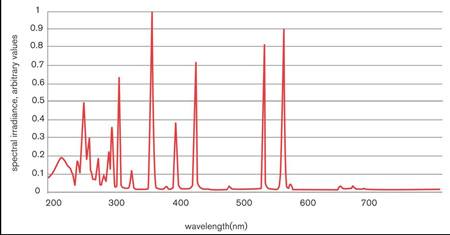
Figure 5 - Typical MP lamp Output Wavelengths
So now that we know that dose is intensity x time, and we understand light sources, we can design our system, right? Sort of.
The dose can be delivered is various ways. A low system intensity (few lamps) and with a low flow rate can achieve the target dose. However, if a higher flow rate is required, more intensity is required to achieve the same dose as the targeted organism is typically in the UV system for a shorter period of time. We can either add more lamps or select a more powerful lamp. So now we can select the best lamp type, and number of lamps needed, in order to achieve the dose required in the most reliable, low cost and practical way possible?
But, no, we can't yet.
We must first take into account other factors, such as the UVT or light transmittance of the water at the wavelength the lamps operate at - 254nm. Visual light transmittance is not UVT.
UltraViolet Transmittance, usually referred to as UVT, is the percentage of light at 254nm that can go through a 1cm water layer of the water in question. While many factors can affect system design, UVT is probably the most misunderstood factor, and one of the biggest influences on system design. It is also one of the biggest factors that, if not accurately determined and accounted for, can cause the UV system to not be able to deliver the dose required. UVT is basically the measure of how much other elements in the water absorb UV-C. If this UV-C is absorbed by non-target organisms, it cannot do the work. UVT is measured with a specialized meter.
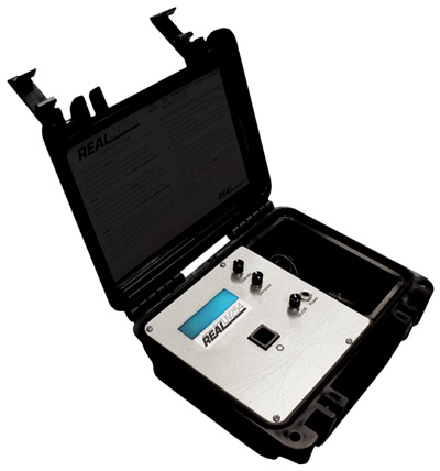
Figure 6 - Cuvette UV Meter (Courtesy of RealTech)
Here is a rough analogy - If you are trying to read a poster just in front of you at night, but the light comes from across your yard from the top of a light standard, you will need a certain amount of visible light to be able to read it. If, however, there is in addition a light fog present, you will need much more light to be emitted. The fog is preventing your light source from doing the job intended-you need more light in order to complete the same task.
While turbidity may affect UVT, it is related to visible light transmission; remember, UVT is only related to the transmittance of photons in water at 254nm. Even visually clear water may have low UVT, dependent on the contaminants present.
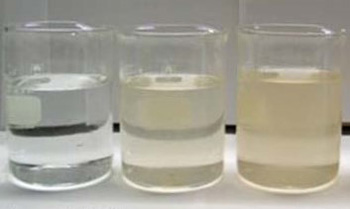
Figure 7 - Turbidity Is Not UVT
As mentioned, when designing a UV system, the output of the lamp is used to determine the dose. Experienced and principled suppliers always design their UV systems based on the output of the lamp at the listed End-Of-Lamp-Life (EOLL), which is described in lamp hours. A 12,000-hour lamp, for example, has its UV-C output measured at that time for system design and sizing purposes.
By designing a UV system with EOLL UV-C output values, the engineer is then confident that the lamp, and thereby the system, will always deliver the minimum, or more, intensity and subsequent dose required.
Past the rated lamp lifetime, the dose requirement may not be met as the lamp UV-C output will be less than required. Typically, UV-C lamp output at end of lamp life is about 80-to-90 percent, as compared to a new lamp. This number however is not very important as the system design takes this into account-you will always have the required intensity, or more, if you change your lamps at end-of-lamp-life. UV-C output degradation is considered to be fairly linear over the lamp lifetime.
A system quote that comes in with very few lamps, as compared to other quotes, is likely not designed with end of-lamp-life taken into account. This means that, while you may receive proper dose at the beginning of lamp life, as soon as hours are accumulated on the lamps and output begins to drop, your system will not be providing the required dose!
If you targeted a three-log reduction of a specific organism you will receive that when the lamps are brand new, but as soon as the lamps age at all you will be delivering less than that requirement. Systems with EOLL taken into account will always deliver the minimum required dose or more.
Fouling on the quartz lamp sleeve can block the passage of UV-C light. It can be biological or mineral-based. If you do not service your system as required, you are effectively reducing your applied UV-C intensity as it is blocked from getting to the water. Principled system designers add a small fouling factor to the system size so that the customers water receives the proper dose when the sleeves are slightly fouled between maintenance cycles.
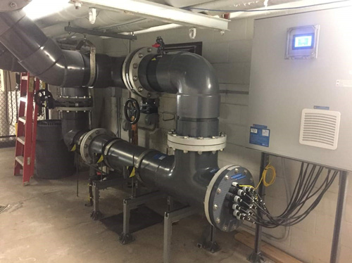
Figure 8 - RK2 Pro-Tect Installation
Your application - Single pass, multi-pass (recirculation), etc.
Disinfection Flow Rates - Normal, peak, do you have times with no flow? Do you ever flow water through the unit at higher than disinfection flow rates?
Treatment Targets - Organisms of concern, UV-C delivered dose requirements.
Water Quality - UVT, turbidity.
Water temperature - Minimum and maximum required and present.
Installation Location - Indoors, outdoors, space availability for maintenance, i.e. lamp removal
Lamp or System Orientation - Vertical or horizontal.
The above information is the basic information required in order to design a UV system for your application. You supplier will also have other questions they can assist you in answering and will also help you to understand the 'why' behind your system design - as well as the 'what'.
Previously, we have discussed how to properly size and design a UV treatment system. RK2 can also help you determine, clarify and solidify the factors that will drive the system design. Did you know that many of these factors can change throughout the year? Care is taken to ensure that you, the customer, will have a UV system that protects your investment.
But what about service and support? One of the keys to a satisfied customer market is the support after the sale. Be it maintenance support, parts or just advice about the use and care of your UV system, a good supplier will always be there in a timely way to help you.